Global sourcing in 2026 will demand more than a familiar motor specification. Buyers must match the Stepper Driver with load inertia, speed range, voltage, heat limits, and control architecture. A compact NEMA 17 machine may need a different driver from a larger packaging axis, even when both use two-phase motors. Small details matter.
Dr. Takashi Kenjo, a recognized author on stepping motors, described the principle simply: “A step motor rotates step by step.” That clarity still guides modern selection. Permanent-magnet drivers suit straightforward, cost-sensitive equipment. Variable-reluctance designs serve specialized applications. Hybrid stepper systems remain popular for their useful torque and positioning accuracy. Closed-loop Stepper Driver systems add encoder feedback, reducing missed-step risk. Integrated drivers can save panel space, but they may complicate replacement planning.
For global sourcing, engineers should compare microstepping quality, current regulation, thermal protection, communication protocols, documentation, and tested operating curves. UL, CE, UKCA, RoHS, and EMC evidence may influence regional acceptance, but certificates alone do not prove field performance. Ask for samples.
Supplier resilience also deserves attention. Dual-source components, firmware ownership, lead-time records, and spare-unit policies can protect production continuity. Yet one assumption deserves review: the cheapest driver is rarely the lowest-cost choice. A noisy cabinet, excessive heat, or unstable low-speed motion can erase the original saving. Some comparisons remain imperfect because suppliers publish different test conditions. This guide therefore focuses on practical evidence, not attractive headline ratings, while examining the top Stepper Driver types for reliable international procurement in 2026.
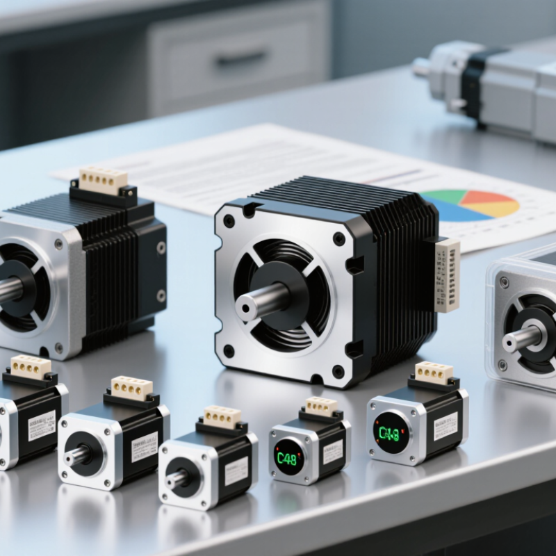
For global sourcing in 2026, stepper driver selection often begins with the step-angle standard.
The smaller angle can produce finer positioning and smoother low-speed motion, but it does not automatically deliver higher accuracy. Mechanical backlash, shaft alignment, load changes, and motor heating still influence the result. Real performance depends on the complete motion system.
When comparing drivers, check rated motor current, supply-voltage range, microstepping control, protection functions, and heat dissipation. A driver must match the motor winding current without excessive heating. Microstepping can reduce vibration, yet it cannot create unlimited usable resolution under heavy loads.
In production tests, I would inspect movement at startup, slow travel, rapid reversal, and continuous duty. Listen for resonance near mid-speed. Check the enclosure temperature after several hours. A neat specification sheet can still mislead.
I have seen apparently suitable combinations lose steps because the current setting was treated as a guess. Wiring quality also deserves attention. Confirm connector orientation, cable length, shielding, and replacement availability before placing a large order. Fit matters.
For 1.8° and 0.9° systems, a small pilot batch can reveal noise, thermal drift, and actual positioning behavior before global volume purchasing.
2026 Top Stepper Driver Types for Global Sourcing
Bipolar and unipolar drivers control two-phase stepper motors differently. A bipolar driver reverses current through each winding with an H-bridge circuit. This uses the full copper winding and usually produces stronger holding torque. It also demands accurate current regulation, suitable transistors, and careful heat management. The difference is practical.
A unipolar driver uses center-tapped windings and switches current through one half of each phase. Its circuit can be simpler and easier to assemble. However, only part of the winding works at one time, which can reduce torque and copper utilization. Unipolar systems may suit compact, cost-sensitive equipment with modest load changes. Bipolar systems often fit robotics, valves, and positioning tables needing higher torque from limited motor size.
Global sourcing teams should compare phase current, supply voltage, connector wiring, and thermal limits together. A motor marked “two phase” does not identify its driver architecture. Confirm the wire count and winding resistance with the supplier. Then test the motor at startup, low speed, and sudden load changes. Measure the driver case temperature after continuous operation. Small details matter.
In field evaluations, bipolar control often delivers smoother microstepping when current decay is well designed. Poor tuning can still create noise and missed steps. Unipolar control may appear stable during light testing but weaken under acceleration. That mistake is common. I would not select by unit price alone. A neat specification can still mislead when airflow, cable length, and production variation are ignored.
For global sourcing in 2026, stepper drivers should be judged by motion quality, heat control, and controller compatibility. Full-step control delivers strong holding torque and straightforward setup. It can also create noticeable vibration and audible resonance. It is simple.
Half-step operation reduces these effects without greatly increasing system complexity. Microstepping divides each motor step into smaller electrical positions. Common options include 1/4, 1/8, 1/16, 1/32, and 1/256 resolution. In bench testing, 1/16 often provides a practical balance between smooth travel and usable torque. Higher settings can reduce vibration, but they do not automatically create equal mechanical accuracy.
Be realistic. A 1/256 command may require many pulses from the controller. Poor pulse timing, shaft flex, or load changes can still cause visible errors. When comparing suppliers, request current-range data, thermal test results, pulse-frequency limits, and sample units for evaluation. Check performance at low speed, acceleration, and continuous operation. Open-loop drivers may suit stable loads, while closed-loop designs can correct certain position losses. I have found that quiet movement sometimes hides weak torque reserves. That detail deserves attention. Before approval, test the chosen microstepping level with the actual motor, wiring length, power supply, and load. Supplier documents are useful, but measured results should guide the final purchase.
Microstepping Choices: From Full-Step Control to 1/256 Resolution
Based on a common 1.8° stepper motor, the chart shows the mechanical angular increment produced by each microstepping setting. Higher microstep ratios provide finer command resolution, while actual positioning accuracy and torque smoothness depend on motor construction, load, current control, mechanical backlash, and system tuning.
Integrated, External, and Closed-Loop Drivers for Global Applications
Integrated stepper drivers combine the controller and power stage in one compact unit. They simplify wiring inside small machines and reduce cabinet space. They suit compact conveyors, laboratory instruments, and lightweight automation equipment. However, heat has fewer escape routes. A supplier should provide thermal data, current limits, and tested operating curves.
External drivers offer more installation flexibility. They can use larger heat sinks, replaceable cables, and different control interfaces. This design fits industrial equipment with longer wiring distances or higher motor currents. During sourcing, check input voltage ranges, pulse response, connector standards, and enclosure protection. Documentation quality matters. A clear wiring diagram can prevent costly assembly mistakes.
Closed-loop drivers add encoder feedback to monitor motor position and detect missed steps. They support demanding applications such as indexing tables, inspection stages, and vertical axes. They may improve reliability, but they also increase cost, software complexity, and setup time. Space is expensive. Global buyers should request sample testing across voltage, temperature, and load conditions. Verify alarm outputs, communication protocols, firmware access, and regional compliance documents before volume orders. In supplier reviews, I have seen impressive laboratory results fail under dusty production conditions. My earlier checklists also overlooked cable quality. That mistake showed why the motor, driver, encoder, and machine should be evaluated as one system.
For global sourcing in 2026, stepper drivers rated from 24 to 80 VDC deserve careful technical screening. The voltage label alone is not enough. Check continuous current, peak current, thermal derating, and regeneration behavior. A 48 VDC driver may deliver stronger acceleration, but poor cooling can reduce its usable output. IEC 61800-3 separates drive systems by electromagnetic environment, making EMC testing essential for machinery shipped across regions.
RoHS compliance should be verified through a current declaration, material records, and supplier test evidence. The European Union RoHS framework restricts 10 substances, including lead, mercury, cadmium, and four phthalates. A 2024 European Commission evaluation also emphasizes stronger supply-chain documentation and market surveillance. Do not accept a simple “RoHS available” statement. Ask for test dates, laboratory scope, and component-level traceability. It is a small detail, but missing records can delay customs or customer approval.
Tips: Build a sourcing checklist around 24, 48, 60, and 80 VDC operating points. Request EMC results under IEC 61800-3, not only internal factory tests. Confirm conducted emissions, radiated emissions, immunity, and grounding instructions. Also inspect the driver at 40°C and 50°C ambient conditions. Some datasheets look impressive at 25°C. Real cabinets are rarely that comfortable. Independent verification remains valuable, because supplier documents can be accurate yet incomplete.
| Stepper Driver Type | Typical DC Input Rating | Typical Phase-Current Range | Motor Compatibility | Microstepping Capability | Control Interfaces | Typical Application Fit | EMC Sourcing Criteria | RoHS Compliance Checkpoints | Global Sourcing Priority |
|---|---|---|---|---|---|---|---|---|---|
| Open-Loop Constant-Current Chopper Driver | 24–48 VDC Some variants: up to 80 VDC |
Approximately 1.0–8.0 A RMS per phase, depending on thermal design | Two-phase bipolar stepper motors, including common NEMA-frame and metric-frame motors | Typically 1/2 to 1/256 step; verify whether the highest settings are interpolated or fully generated | Pulse/direction; optional enable and alarm inputs | Cost-sensitive positioning, conveyors, indexing tables, laboratory equipment, and general automation | Request conducted and radiated-emission test data; check cable-shielding, grounding, switching-frequency, and enclosure recommendations | Require a current RoHS declaration covering restricted substances under Directive 2011/65/EU and amendment (EU) 2015/863; verify homogeneous-material documentation when required | Best valueBroad availability |
| High-Voltage Open-Loop Driver | 48–80 VDC nominal operating range | Approximately 2.0–10.0 A RMS per phase; confirm continuous and peak definitions | Two-phase stepper motors requiring higher speed or improved high-speed torque | Typically 1/2 to 1/128 or higher, depending on controller architecture | Pulse/direction; enable, fault, and sometimes programmable current inputs | Longer travel, higher bus voltage systems, machine tools, packaging, and high-speed indexing | Check maximum bus-voltage transients, regenerative-energy handling, common-mode noise, EMC filter requirements, and protective-earth arrangement | Confirm RoHS status for the driver, terminal blocks, fan, cable assemblies, and any supplied accessories rather than only the main PCB | High-speed priorityThermal review required |
| Closed-Loop Hybrid Stepper Driver | 24–48 VDC typical Higher-voltage models may support 60–80 VDC |
Approximately 2.0–12.0 A RMS per phase, depending on motor size and feedback system | Hybrid stepper motors with incremental encoder feedback, commonly 2-phase systems | Typically 1/2 to 1/256 step; actual position correction depends on encoder resolution and control firmware | Pulse/direction; encoder input; alarm output; some versions add serial configuration | Applications needing reduced stall risk, lower idle heating, and improved load monitoring | Evaluate encoder-cable immunity, shield termination, fault behavior, motor-cable length, and compliance testing with the feedback cable installed | Request declarations for the driver and encoder assembly; verify that solder, cable insulation, connectors, and shielding materials are included in the compliance scope | Reliability priorityLower stall risk |
| Integrated Stepper Motor Driver | 24–48 VDC typical | Approximately 1.0–6.0 A RMS per phase, limited by motor housing and thermal dissipation | Stepper motor and driver supplied as one integrated motion unit | Typically 1/2 to 1/256 step, subject to the integrated controller | Pulse/direction, RS-485, CAN, or other serial communication depending on the design | Compact machines, modular axes, robotics subsystems, and applications with limited cabinet space | Assess radiated emissions from the motor-mounted electronics, connector shielding, heat dissipation, and EMC behavior in the final machine enclosure | Obtain a product-level RoHS declaration and clarify whether the motor, cable, connector, encoder, and mounting hardware are covered | Space savingSimplified wiring |
| Programmable Digital Stepper Driver | 24–60 VDC typical Some industrial versions support 80 VDC |
Approximately 2.0–8.0 A RMS per phase | Two-phase stepper motors with configurable current, acceleration, resonance, and protection parameters | Typically 1/2 to 1/512 step; confirm whether settings are native, interpolated, or command-scaled | Pulse/direction plus USB, RS-485, CAN, or configuration software | OEM equipment requiring repeatable setup, parameter locking, diagnostics, and field-service access | Request EMC test conditions, firmware-controlled switching settings, alarm filtering behavior, and immunity results for ESD, EFT, and surge | Check revision-controlled declarations, material change notification procedures, and documentation retention for long-term OEM sourcing | OEM preferredDiagnostic capability |
| Networked Stepper Drive | 24–48 VDC typical Higher-voltage versions may reach 80 VDC |
Approximately 2.0–10.0 A RMS per phase | Open-loop or closed-loop stepper motors, depending on the networked drive design | Typically 1/2 to 1/256 step | CANopen, EtherCAT, Modbus RTU, or another industrial fieldbus; verify protocol profile and connector pinout | Multi-axis automation, synchronized motion, distributed control cabinets, and machine networking | Check fieldbus-cable shielding, galvanic isolation, grounding topology, EMC performance at maximum network traffic, and network recovery after interference | Request RoHS evidence for the drive, communication connectors, isolation components, and optional communication cables | Multi-axisSystem integration |
| Low-Voltage Compact Driver | 24 VDC nominal Typical operating range: approximately 18–30 VDC |
Approximately 0.5–3.0 A RMS per phase | Small two-phase stepper motors used in compact mechanisms | Typically 1/2 to 1/128 step | Pulse/direction; simple enable and fault signals | Small actuators, valve positioning, compact instruments, feeders, and battery-backed equipment | Check susceptibility to supply ripple, fast transients, motor-lead emissions, and immunity in plastic or space-constrained enclosures | Confirm RoHS coverage for compact connectors, cable insulation, solder materials, and any supplied heat sink or mounting plate | Compact design24 VDC standardization |
| Safety-Oriented Stepper Driver | 24–48 VDC typical | Approximately 1.0–8.0 A RMS per phase | Stepper motors in equipment requiring controlled disable or monitored fault behavior | Typically 1/2 to 1/256 step | Pulse/direction plus enable, fault, and possibly a dedicated safe-disable input | Industrial machinery where controlled motor de-energization and fault reporting are important | Separate EMC evidence from functional-safety evidence; verify ESD, EFT, surge, conducted emissions, and behavior during power interruption | Request a product-specific RoHS declaration and material-change controls; do not treat RoHS compliance as a substitute for safety certification | Machine safetyDocumentation priority |
Notes: Voltage and current values are representative sourcing ranges rather than universal specifications. Final selection should be based on the motor phase inductance, required speed–torque curve, duty cycle, ambient temperature, enclosure, regeneration, cable length, and the applicable regional standards. For industrial equipment, commonly reviewed EMC frameworks include IEC 61800-3, IEC 61000-6-2, and IEC 61000-6-4, subject to the final product classification and installation environment. RoHS verification should reference Directive 2011/65/EU and amendment (EU) 2015/863, with supplier documentation matching the exact model and revision.
A 1.8° motor completes 200 full steps per revolution. A 0.9° motor completes 400. A smaller step angle can improve positioning and low-speed smoothness. It does not guarantee higher accuracy.
No. Backlash, shaft alignment, heating, and changing loads still affect actual positioning. The complete motion system matters more than the angle alone.
Check motor current, supply-voltage range, microstepping options, protection functions, and heat dissipation. The driver must match winding current carefully. Guessing the current setting can cause missed steps.
1/16 often balances smooth movement, vibration control, and usable torque. Higher settings may sound better. They do not create unlimited mechanical resolution.
No. It can require many controller pulses and may reduce practical torque reserves. Poor timing, shaft flex, and load changes can still create visible errors. More resolution is not always more accuracy.
Full-step control offers strong holding torque and simple setup. It may also produce louder vibration and mid-speed resonance. Simple, but not always smooth.
Use a pilot batch with the actual motor, wiring, power supply, enclosure, and load. Test startup, slow travel, rapid reversal, acceleration, and continuous operation. Check temperature after several hours.
Confirm connector orientation, cable length, shielding, and replacement availability. Poor wiring can introduce noise or unstable motion. I sometimes underestimate this detail. That is a mistake.
Open-loop control may suit stable loads and simpler systems. Closed-loop designs can correct certain position losses. Quiet motion can still hide weak torque reserves. Test real loads before approval.
This guide explains the key Stepper Driver types and selection factors for global sourcing in 2026. It begins with the two common step-angle standards: 1.8° for general motion control and 0.9° for finer positioning. It then compares bipolar and unipolar architectures, focusing on how two-phase current control affects torque, wiring, efficiency, and system complexity.
The article also reviews microstepping options, ranging from full-step operation to resolutions as high as 1/256, helping engineers balance smooth movement, accuracy, and control requirements. It further distinguishes integrated, external, and closed-loop drivers for different application sizes and performance levels. For international procurement, buyers should evaluate 24–80 VDC operating ratings, thermal performance, EMC characteristics, documentation, production consistency, and RoHS compliance. These criteria support reliable integration across automation, robotics, positioning equipment, and other industrial systems while reducing compatibility and sourcing risks.
