What Is a Gear Reduction Motor and How Does It Work?

Time:2026-10-07 Author:Aria
0%

A Gear Reduction Motor combines an electric motor with a gearbox to deliver slower, stronger rotation. The motor spins quickly, but many machines need controlled torque instead. The gearbox changes that relationship through carefully selected gear ratios. As mechanical design authority Robert L. Norton explains, “Gear trains transmit motion and power while changing speed and torque.” That principle sits at the heart of nearly every gearmotor application.

Imagine a conveyor carrying a heavy box. A bare motor may turn too quickly and struggle under load. A Gear Reduction Motor can rotate the roller more slowly, while producing useful pulling force. This trade-off is practical, not magical. Speed decreases. Torque increases. Some energy is also lost through friction, bearing resistance, and heat. Real systems are messier.

This guide explains the internal parts, operating sequence, reduction ratios, and common motor types. It also examines efficiency, backlash, noise, lubrication, and service life. These details matter when selecting a motor for robotics, factory equipment, lifts, or automated gates. A larger ratio does not automatically create a better solution. It may increase torque while reducing output speed and responsiveness. That distinction is easy to miss.

Specifications deserve careful checking. Rated torque, peak torque, duty cycle, voltage, mounting position, and operating temperature can change performance significantly. Measurements from a real application often reveal problems that catalog numbers hide. Even experienced designers occasionally choose too much capacity. More power can mean more cost, weight, and wasted energy. Understanding those compromises makes Gear Reduction Motor selection more reliable.
What Is a Gear Reduction Motor and How Does It Work?

What Is a Gear Reduction Motor?

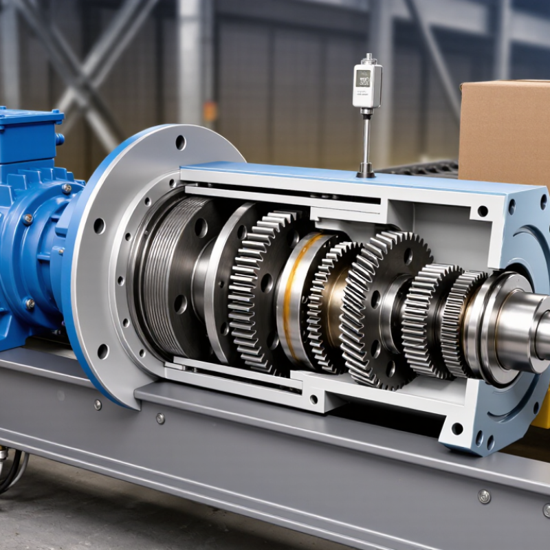
A gear reduction motor combines an electric motor with a gearbox in one working unit. The motor spins quickly, while the gearbox slows that rotation before it reaches the output shaft. This reduction increases usable torque, allowing the motor to move heavier loads with controlled force. More torque, less speed.

Inside the gearbox, several gears transfer motion through different tooth sizes. A small driving gear turns a larger driven gear, reducing output speed at a predictable ratio. For example, a 20:1 reduction may produce roughly one output revolution for every twenty motor revolutions. The actual result depends on efficiency, friction, and the applied load. It is not perfectly simple.

A gear reduction motor suits conveyors, lifting mechanisms, rotary tables, and automated valves. In practical testing, the output shaft may turn steadily while carrying a 10-kilogram load. However, a technician must check starting torque, duty cycle, temperature, and shaft strength. A gearbox can multiply torque, but it cannot create unlimited power. If the reduction ratio is too high, movement may become slow and inefficient.

The housing may use spur, helical, planetary, or worm gears. Each design changes noise, backlash, efficiency, and holding behavior. Worm gears can resist back-driving, but they may generate more heat. I have found that selecting a motor by speed alone often causes trouble. Load changes, repeated starts, and poor alignment can shorten service life. Testing the complete assembly under real conditions reveals weaknesses that a specification sheet may miss.

What Is a Gear Reduction Motor and How Does It Work?

A gear reduction motor combines an electric motor with a gearbox to reduce output speed and increase torque. This chart uses a 1,800 rpm motor producing 0.5 N·m of input torque and assumes 90% gearbox efficiency. Output speed is calculated as motor speed divided by the gear ratio, while output torque is estimated from motor torque × gear ratio × efficiency.

As the reduction ratio increases, the motor's output shaft turns more slowly but delivers substantially more torque, making gear reduction motors suitable for conveyors, lifting mechanisms, robotics, and other low-speed applications.

What Are the Main Components of a Gear Reduction Motor?

What Is a Gear Reduction Motor and How Does It Work?

A gear reduction motor combines an electric motor with a gearbox. The motor produces speed. The gearbox trades speed for torque through meshing gears. This arrangement moves heavy loads more slowly and with better control. The International Energy Agency reports that motor-driven systems consume about 53% of global electricity. Therefore, efficiency and correct sizing deserve close attention.

What Are the Main Components of a Gear Reduction Motor?

The motor, gearbox, shafts, bearings, seals, housing, lubricant, and output coupling form the working core. The motor’s rotor turns the input shaft. Gear stages then reduce rotational speed and increase output torque. Bearings support the shafts and limit friction. Seals keep lubricant inside while blocking dust and moisture. The housing holds alignment under load. Helical, planetary, and worm gears behave differently. Their efficiency, noise, heat, and allowable load are not interchangeable. A 2023 U.S. Department of Energy assessment also notes that efficient motor systems can reduce industrial energy use significantly, although real savings depend on duty cycles and maintenance.

Tips: Check the required output torque, speed, duty cycle, and mounting position. Confirm the service factor. Inspect lubricant, seals, and unusual vibration regularly. I have seen oversized units waste energy, while undersized units overheat. Gear ratio alone does not guarantee performance. Temperature, shock loading, and alignment can change the result. A simple selection shortcut may look practical, but it can become an expensive mistake.

How Does a Gear Reduction Motor Work Step by Step?

A gear reduction motor combines an electric motor with a gearbox. The motor spins quickly, but it produces limited torque. The gearbox changes that balance. It lowers speed and increases turning force at the output shaft.

The process starts when electrical current creates a magnetic field inside the motor. This field turns the rotor and its small input gear. That gear meshes with a larger gear inside the gearbox. Because the larger gear turns fewer times, rotational speed decreases. Its available torque increases at the same time.

Several gear pairs may repeat this action. Each pair adds more reduction. The final gear drives the output shaft, which moves a wheel, conveyor, valve, or other load.

The real process is less tidy. Friction, heat, and small gaps between teeth reduce efficiency. A heavy load can make the motor draw more current. The housing may also become warm during continuous operation. A practical check includes measuring shaft speed, listening for unusual noise, and checking temperature after running. Good lubrication helps, but too much lubricant can also create resistance. Backlash may cause a slight movement before the load responds. This detail is often ignored in simple diagrams. Gear alignment matters too. Even a strong motor can perform poorly when the output shaft carries a side load. For reliable operation, match the reduction ratio, torque rating, duty cycle, and load inertia instead of judging the motor by speed alone.

What Are the Benefits and Limitations of Gear Reduction Motors?

A gear reduction motor combines an electric motor with a gearbox. The gearbox lowers output speed and increases usable torque. For example, a 20:1 ratio can turn one shaft revolution into twenty motor revolutions. Gear teeth transfer motion through several stages. Each stage also introduces friction.

Its main benefit is practical torque. A small motor can move a heavy conveyor, lift mechanism, or rotary table without demanding an oversized motor. This saves installation space and may reduce equipment cost. The U.S. Department of Energy reports that motor-driven systems consume about 69% of industrial electricity in the United States. Better sizing therefore matters. The International Energy Agency has estimated that electric motor systems use roughly 46% of global electricity. A reduction gearbox cannot erase that energy demand, but correct ratios can prevent inefficient oversizing.

The trade-off is efficiency loss. A gearbox produces heat, noise, backlash, and mechanical wear. Lubricant quality and alignment strongly affect service life. High ratios may also slow response, which can frustrate precise positioning. Some systems need a brake or encoder. Gearboxes are not magic.

In field maintenance, I have seen a motor run smoothly while a dry bearing caused the real problem. That mistake is easy to repeat. Published efficiency values also vary with load, temperature, lubrication, and measurement method. Engineers should check actual duty cycles, starting torque, shock loads, and maintenance access before choosing a reduction motor.

Where Are Gear Reduction Motors Commonly Used?

Gear reduction motors combine an electric motor with a gearbox. The gearbox lowers speed and increases torque. This helps machines move heavier loads with better control. In practical testing, the output shaft often turns slowly but steadily. That stability matters when sudden movement could damage parts.

These motors are common in conveyor systems, packaging equipment, automatic doors, and adjustable furniture. Small versions operate window openers, camera mounts, and vending mechanisms. Larger units drive mixers, lifts, and material-handling equipment. Designers choose them by checking torque, speed, duty cycle, and available space. A motor that works well for a light conveyor may fail in a lifting system. Heat, noise, and repeated starts also affect service life. I have found that real operating conditions sometimes differ from catalog estimates. That difference deserves careful review.

Tips: Match the gearbox ratio to the required output speed. Measure the starting load, not only the running load. Allow ventilation around the motor. Check alignment before installation. Regularly inspect mounting bolts, seals, and unusual noise. Oversizing may improve durability, but it can waste energy and space. Undersizing is worse. It may cause overheating, slow movement, or early gear wear. A simple load test can reveal problems before full production.

FAQS

What is a gear reduction motor?

It combines an electric motor and gearbox in one unit. The motor spins quickly, while the gearbox lowers speed and increases torque. More torque, less speed.

How does the gearbox change motor performance?

Small gears drive larger gears, reducing output speed through a predictable ratio. A 20:1 ratio may produce one output revolution per twenty motor revolutions. Actual results vary with friction, efficiency, and load.

What are the main components?

The main parts include the motor, gearbox, shafts, bearings, seals, housing, lubricant, and output coupling. Bearings support rotating shafts. Seals help keep out dust and moisture.

Where are gear reduction motors commonly used?

They drive conveyors, lifting mechanisms, rotary tables, automatic doors, mixers, and adjustable furniture. Smaller units may operate window openers or camera mounts. Applications vary widely.

How should the correct motor be selected?

Check output torque, speed, starting load, duty cycle, mounting position, and available space. Confirm the service factor. Gear ratio alone does not guarantee performance.

Can a gear reduction motor create unlimited power?

No. A gearbox increases usable torque by reducing speed, but it cannot create unlimited power. Excessive reduction can make movement slow and inefficient. This is easy to overlook.

How do gear designs affect performance?

Spur, helical, planetary, and worm gears differ in noise, heat, efficiency, backlash, and holding behavior. Worm gears may resist back-driving but generate more heat. The simple answer is incomplete.

What maintenance problems should be checked?

Inspect lubricant, seals, mounting bolts, alignment, temperature, and unusual vibration. Repeated starts and poor alignment can shorten service life. A short load test can reveal hidden weaknesses.

What common sizing mistakes should be avoided?

Choosing by speed alone can cause overheating or early gear wear. Undersized units may fail under starting loads. Oversized units can waste energy and space. I would test real conditions before trusting a specification sheet.

Conclusion

A Gear Reduction Motor combines an electric motor with a gearbox to deliver slower rotation and higher torque than the motor can produce on its own. Its main components typically include the motor, gear set, shafts, bearings, housing, and power connections. When electricity reaches the motor, it creates rotational force. This motion enters the gearbox, where interacting gears reduce the output speed while multiplying torque. The final shaft then transfers controlled mechanical power to the connected equipment.

Gear Reduction Motors offer strong starting force, improved control, compact power transmission, and reliable operation in many mechanical systems. However, they may be heavier, less efficient, noisier, and more complex than direct-drive motors, especially when gear friction and maintenance are considered. They are commonly used in conveyors, lifting mechanisms, automated machinery, robotics, adjustable equipment, vehicle systems, and household devices. Their suitability depends on required speed, torque, operating time, load conditions, and available installation space.

Aria

Aria

Aria is a dedicated marketing professional with a deep passion for innovative strategies and a keen understanding of our company's product offerings. With a wealth of experience in the industry, Aria excels at crafting engaging content that highlights the unique features and benefits of our......